The RealSimGear G500 avionics have a number of configurable options to change certain aspects of the the avionics for installation into any aircraft. This will allow you to tailor speeds, map options, and more for your individual aircraft.
The purpose of this guide is to cover what each of these settings are in the G500.cfg file.
Note: This guide is tailored to more advanced users of X-Plane. Editing of configuration files can cause unwanted effects or possible game crashes of X-Plane if not configured properly.
Autopilot Integration Steps
X-Plane 11:
Changes that need to be made in the aircraft file (through PlaneMaker):

In PlaneMaker open the .acf file for the aircraft:
-
Go to: -> Standard -> Systems -> General 1, set:
-
Set AP heading to AHRS
-
Check pilot and copilot side Auto Adjust CDI to GPS DTK.
X-Plane 12:
In PlaneMaker open the .acf file for the aircraft:
-
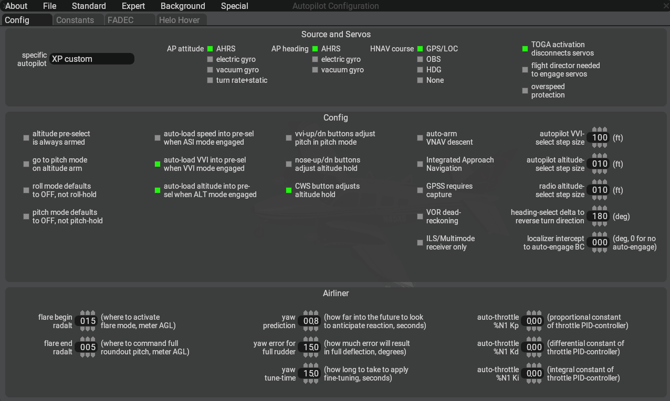
Go to: -> Expert -> Autopilot Configuration
- Set AP attitude to AHRS
- Set AP Heading to AHRS
- Set HNAV to GPS/LOC
Tip: PlaneMaker is a utility that is included with the installation of X-Plane. You will find it in the main installation folder of X-Plane.
Configuration Files
The main configuration file is g500.cfg that lives in the main aircraft folder (next to the .acf files). This file contains the aircraft relevant information for the integration. Here are entries in this file used on our included default C172 integration.
| mfd_ownship | This is the image used as the aircraft icon on the moving map. The options available can be found in Appendix A |
| pfd_radio_altimeter_enabled |
Radio altimeter equipped: [0] Not equipped, [1] Equipped |
| pfd_vs_range |
Vertical speed indicator range: [0] ±2000 fpm, [1] ±3000 fpm, [2] ±4000 fpm |
| power_dataref | By default, the G500 looks at the default X-Plane battery dataref to determine power. Choose a different integer-based dataref if you wish to override this (or make your own). Reading dataref: [0] off, [Any non-zero integer] on |
| render_mfd_h |
Height (in pixels) of MFD render on panel texture Native height: 768px Set to 0 to disable rendering |
| render_mfd_w |
Width (in pixels) of MFD render on panel texture Native width: 512px Set to 0 to disable rendering |
| render_mfd_x | X-Coordinate (in pixels) of the left edge of the MFD render on panel texture (measured from left edge of panel texture) |
| render_mfd_y | Y-Coordinate (in pixels) of the bottom edge of the MFD render on panel texture (measured from bottom edge of panel texture) |
| render_pfd_h |
Height (in pixels) of PFD render on panel texture Native height: 768px Set to 0 to disable rendering |
| render_pfd_w |
Width (in pixels) of PFD render on panel texture Native width: 512px Set to 0 to disable rendering |
| render_pfd_x | X-Coordinate (in pixels) of the left edge of the PFD render on panel texture (measured from left edge of panel texture) |
| render_pfd_y | Y-Coordinate (in pixels) of the bottom edge of the PFD render on panel texture (measured from bottom edge of panel texture) |
| v_config_1 | V1 speed to draw label on airspeed tape |
| v_config_2 | V2 speed to draw label on airspeed tape |
| v_config_fe | VFE speed to draw label on airspeed tape |
| v_config_g | VG speed to draw label on airspeed tape |
| v_config_le | VLE speed to draw label on airspeed tape |
| v_config_line_blue | Blue Line to draw on airspeed tape (used in multi-engine aircraft) |
| v_config_line_red | Red Line to draw on airspeed tape (used in multi-engine aircraft) |
| v_config_ne | VNE speed, drawn as top of red arc on airspeed tape |
| v_config_no | VNO speed, drawn as top of green arc and start of yellow arc on airspeed tape |
| v_config_r | VR speed to draw label on airspeed tape |
| v_config_rf | VRF speed to draw label on airspeed tape |
| v_config_s0 | VS0 speed, drawn as top of low speed red arc and start of white arc on airspeed tape |
| v_config_s1 | VS1 speed, drawn as bottom of green arc on airspeed tape |
| v_config_x | VX speed to draw label on airspeed tape |
| v_config_y | VY speed to draw label on airspeed tape |
Popup Windows
Both bezeled and non-bezeled popups can be opened via commands. RealSimGear hardware also has some automatic positioning features with the G500. Unless configured to be positioned, on command trigger, the popup will center around the mouse cursor’s current position.
Popup Positioning and Configuring
Popups can be configured in the popups.cfg file located in the aircraft -> plugins -> rsg_g500 -> settings folder.
In this file there are various settings to configure:
| ***_x/y | x/y coordinate when used as popup window |
| ***_w/h | width/height when used as a popup window |
| ***_fill_window |
If set to 1 (default), it will fill the window and alter the aspect ratio (squish) as needed. If set to 0, it will follow current behavior and cut off the top if the window is too short. |
| ***_start |
If RSG finds monitors, the setting will then be set to [2] in the config file.
|
| ***_monitor_start |
|
| ***_x/y | x/y coordinate when used as popup window |
| ***_w/h | width/height when used as a popup window |
| ***_fill_window |
If set to 1 (default), it will fill the window and alter the aspect ratio (squish) as needed. If set to 0, it will follow current behavior and cut off the top if the window is too short. |
| ***_start |
|
| ***_monitor_start |
|
Pop up Controls:
Within the popups themselves, positions can be saved/windows positioned by the following clicks on popup windows:
Top Left Corner:
-
Left Click: Close Window
-
Right Click: Try to go full screen in 2D panel mode (must be set to be 2D Panel monitor in X-Plane settings)
Top Right Corner:
-
Left Click: Popout Window (if coordinates are saved, it will go to those)
-
Right Click: Save current coordinates as popup location
Bottom Left Corner:
-
Left Click (and drag): (Not in popup) Resize in-sim window
-
Right Click: No current functionality
Bottom Right Corner:
-
Left Click (and drag): (Not in popup) Resize in-sim window
-
Right Click: Attempt 2D Panel swap of PFD and MFD. This will only work if the PFD (Bezel-less) and MFD (Bezel-less) are already full screen in the 2D panel mode.
Miscellaneous Configuration Details
In integrations where the G500 could be installed, but not in use, there is a dataref that can be set to disable all G500 drawing and ongoing processes.
Set rsg/g500/general/kill_drawing to 1, disabling the G500s. Setting back to 0 will restore the units to their state at the original disabling.
Setting the G500 Avionics to G500H for use with helicopters
-
Install the G500 avionics into the aircraft as per the RealSimGear G500 Guide
- Load into X-Plane and run the simulation at least once to enable the automatic popout system and configure the basic settings for the avionics.
- Exit X-Plane.
- Navigate to the aircraft installation folder. In this example we have installed the G500 to the Sikorsky S76. ""C:\X-Plane 12\Aircraft\Laminar Research\Sikorsky S-76\"
- In the aircraft folder go to: Plugins -> rsg-g500 -> settings
- Open "popups.cfg"
- Locate the following section:
nbzl_g500hw_combined_620_fill_window = 1
nbzl_g500hw_combined_620_h = 800
nbzl_g500hw_combined_620_monitor_start = -1
nbzl_g500hw_combined_620_popup_at_start = 0
nbzl_g500hw_combined_620_w = 1280
nbzl_g500hw_combined_620_x = 0
nbzl_g500hw_combined_620_y = 0
nbzl_g500hw_combined_fill_window = 1
nbzl_g500hw_combined_h = 800
nbzl_g500hw_combined_monitor_start = 1
nbzl_g500hw_combined_popup_at_start = 2
nbzl_g500hw_combined_w = 1280
nbzl_g500hw_combined_x = 0
nbzl_g500hw_combined_y = 0
-
Adjust your configuration to the following:
nbzl_g500hw_combined_620_h = 800
nbzl_g500hw_combined_620_monitor_start = 1
nbzl_g500hw_combined_620_popup_at_start = 2
nbzl_g500hw_combined_620_w = 1280
nbzl_g500hw_combined_620_x = 0
nbzl_g500hw_combined_620_y = 0
nbzl_g500hw_combined_fill_window = 1
nbzl_g500hw_combined_h = 800
nbzl_g500hw_combined_monitor_start = -1
nbzl_g500hw_combined_popup_at_start = 0
nbzl_g500hw_combined_w = 1280
nbzl_g500hw_combined_x = 0
nbzl_g500hw_combined_y = 0
In the example provided "nbzl_g500_combined_620" is the "H" or helicopter configuration of the G500, with the PFD on the right hand side of the display. We have effectively transferred the automatic popup settings from the standard G500 to the G500H.
Note: The values shown may or may not differ from your system specific configuration. You are only transferring the numerical values of "monitor_start" and "popup_at_start" between the two G5000 types.
Appendix A: Ownship Icons
| 0 | Generic | |
| 1 | High Wing | |
| 2 | Kit | |
| 3 | Low Wing | |
| 4 | Simple | |
| 5 |
|
Twin Prop |
| 6 | Business Jet | |
| 7 | Single Engine Jet | |
| 8 | 2 Blade Helicopter | |
| 9 | 3 Blade Helicopter | |
| 10 | 4 Blade Helicopter |