- One: Quick Start Guide.
- One: RealSimGear GNS530
- One: 12V 2.0 Amp DC Power Adapter with a 5.5mm x 2.1mm barrel connector. (North America socket pattern).
- One: USB A to B cable .
- Four: M3 Self-tapping screws for plastic to secure your device to an appropriate desktop stand.

GNS430 Package Inclusions
- One: Quick Start Guide.
- One: RealSimGear GNS430
- One: USB A to B cable.
- Four: M3 Self-tapping screws for plastic to secure your device to an appropriate desktop stand.
Note: A 12V DC power adapter is not required for the GNS430. This device receives it's power from the USB cable.

Download and install the RealSimGear plugin for your flight simulation software.
You will need the latest version of the RealSimGear Plugin for Microsoft Flight Simulator 2020/2024 . This can be downloaded from the RealSimGear Downloads Center at the following link:
RealSimGear Downloads Center - Downloads for Microsoft Flight Simulator
Installation for the GNS530 and GNS430 into a desktop stand.
The RealSimGear GNS530 and GNS430 are intended to be used in a desktop stand. Additionally, you can use them in a custom panel or mount. RealSimGear provides drawings for mounting in a custom solution here: Panel Dimensions and Cutouts
Installation into a desktop stand is quite simple:
- Insert the device into the RealSimGear Desktop Stand
- Use the four M3x8mm Self tapping screws (included with each device) to secure the device to the stand.
Note: Please use a #2 Phillips Head screwdriver to hand tighten the screws. Do not overtighten the screws.


Setting up the GNS devices in the RealSimGear Interface for Microsoft Flight Simulator:
Before you can properly control the respective GNS units in Microsoft Flight Simulator with your RealSimGear GNS devices, you need to set each GNS device to the appropriate roll in the RealSimGear Plugin Interface.
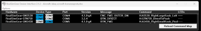
The image above shows a GNS530 and GNS430 Connected to the RealSimGear Plugin for MSFS as well as some additional RealSimGear hardware.
Next to the hardware description are two boxes labelled "COM1" and "COM2", one highlighted in blue, the other in white. The blue highlighted "Device Type" tells the RealSimGear MSFS Plugin what commands each device is sending to the simulator.
For GNS devices to send proper commands:
GNS530: This needs to be set to COM1, highlighted in blue.
GNS430: This needs to be set to COM2, highlighted in blue.
Note: The term "COM1" or "COM2" in the plugin interface, does not refer to what Radio COM channel the device is controlling in the simulator. It is only used by the plugin interface to send the proper commands from the plugin's command mapping file.
This means that if the aircraft you are flying is only equipped with a GNS430, it will still have control over the Com1 radio channel in the simulator, even though it is set to COM2 in the interface.
Moving the Avionics Pop Outs from the Aircraft to the RealSimGear GNS Devices:
There are two methods for providing the avionics pop outs from Microsoft Flight Simulator to the RealSimGear GNS devices:
- Default method using AltGr (right alt key) and a single left click of your mouse.
- Using HawkeyeStan's MSFS Pop Out Panel Manager app for MSFS 2020 and 2024.
RealSimGear strongly recommends using the MSFS Pop Out Panel Manager app as this will prevent the dreaded "lost pop out" issue in MSFS.
We do provide our own setup guide for: Pop Out Panel Manager
Manual Pop Out Method:
- Hold down the Alt-Gr (The ALT key to the right of the space bar) while hovering your mouse over the in-aircraft avionics, your cursor will change to a magnifying glass with a "+" sign and then LEFT click once. This will create a single pop out window of the GNS display near the upper left corner of your main monitor.
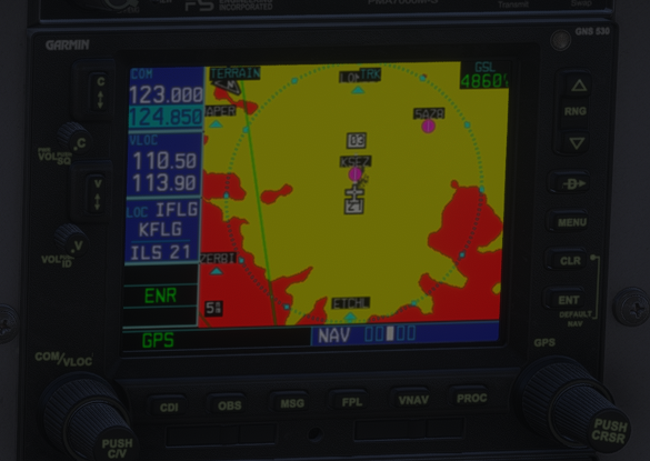
- You will notice that your GNS pop outs have black borders on the left and right edges. We will want to remove them by adjusting the width of the pop out window.
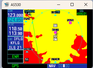
- Hover your mouse cursor over the left or right edge of the window, which ever side is easiest to see the border between the black bar, and the actual display. We do recommend having the third page open on the NAV menu for this step.
- When your mouse cursor changes to a double arrow icon, left click and hold the mouse button.
- Drag the edge of the window in small increments to reduce the width of the window only. Every time you drag the window edge to reduce the width release the left mouse button. This will make the window smaller in width, while maintaining its height.
Tip: If you move the left or right edge of the pop out too much, a black bar may appear at the bottom of the pop out window, simple resize the width back until you see a black bar appear on the sides of the pop out and repeat the width adjustment again.
-
Continue to reduce the width until the black bar is a very small fraction of it's original width.
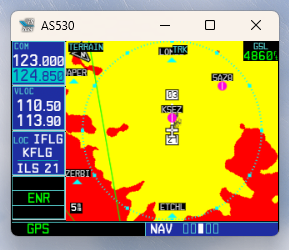
-
With the window resized, left-click and hold the white bar at the top of the pop out window, then drag the window into the center of the respective display (GNS530 in our example).
Tip: You will need to ensure that each pop out is displayed completely in the monitor you wish the pop out display should occupy. No part of the the pop out should be located outside the limits of the display. This is important for the final step. If it is outside the display limits the full screen operation will fail.
To make a manual pop out full screen: Simply move your mouse cursor to that particular display and left click once to bring that display into focus in Windows.
- Next, press Alt Gr (Right ALT key, next to the spacebar) and Enter. This will tell Microsoft Flight Simulator to make that window full screen.
Note: The GNS displays in Microsoft Flight Simulator are actually rendered in the resolution of the real-world GNS unit. When displayed on the RealSimGear GNS displays, the avionics may appear fuzzy. This is normal behavior and not a defect of the RealSimGear devices.